Prepreg Tack Test Fixture (ASTM D8336)
Model No. WTF-PR (Stainless Steel)

Fig. 1: ASTM D8336 Prepreg Tack Test Fixture
This recently standardized (2021) test method focuses on the measurement of surface adhesion, or “tack,” of partially-cured (B-staged) thermoset composite prepreg. The ASTM D8336 test fixture (Fig. 1) includes two pairs of opposing 25 mm diameter rollers attached to the fixture body with low-friction bearings. The front pair of rollers aligns and supports the prepreg specimen whereas the rear pair of rollers provides compaction to the prepreg specimen, simulating the layup process. The compaction force is applied by two springs mounted to the ends of the lower rear compaction roller. The magnitude of the compaction force may be adjusted by rotating the two jacking screws that connect the tops of the compaction springs to the fixture body. The test fixture is attached to the base of a universal testing machine. The upper end of the specimen is inserted into a mechanical vise grip attached to the load cell above the fixture.
Two types of prepreg specimens may be tested (Fig. 2), depending on whether the tack measurement is to be made between two prepreg layers (Method I) or between a prepreg layer and a rigid metal substrate (Method II). In both cases, the prepreg strip is 75 mm (3 in.) wide and at least 215 mm (8.5 in.) long. The rigid substrate, typically a stainless steel plate, is 80 mm (3.15 in.) wide and at least 140 mm (5.5 in.) long.

Fig. 2: Prepreg Specimens for Prepreg Tack Testing.
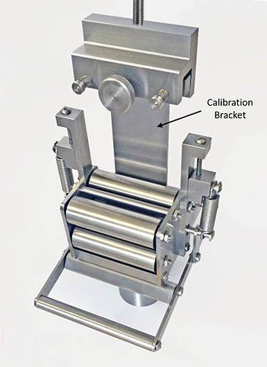
Prior to testing, a calibration procedure is required to relate the number of revolutions of the jacking screws to the applied compaction force. The calibration is performed by mounting an L-shaped steel bracket into the upper grip and positioning the short flange of the bracket directly underneath the compaction roller (Fig. 3). The two jacking screws are tightened incrementally by the same number of revolutions and the resulting force is measured by the load cell up to at least 100 N (22.5 lb). A calibration curve is developed, relating the number of revolutions of the jacking screws to the resulting compaction force.

Fig. 3: Prepreg Tack Test Fixture with Calibration Bracket Installed.
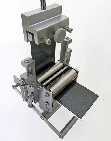
To perform the prepreg tack test, the assembled prepreg specimen is inserted into the test fixture between the two sets of opposing rollers with the extended-length prepreg layer on top. This prepreg layer is deformed upward around the spring-loaded compaction roller and inserted into the upper grip (Fig. 4). As the crosshead of the test machine is raised, a continuous application-and-peel process occurs, as the prepreg is pressed against the substrate under a specified force and subsequently peeled away as the substrate translates horizontally. The applied force and crosshead displacement are measured by the test machine over two phases of the test. In the first phase, the prepreg is covered by a thin film, producing a reduced force due only to friction and bending of the prepreg. The higher force level in the second phase also includes the peeling of the prepreg from a second prepreg layer or the metal substrate. The peel force per unit width is obtained by subtracting the average force from the second phase from the average force from the first phase.

Fig. 4: ASTM Standard D8336 Prepreg Tack Test Fixture, Shown with Prepreg Specimen.
Test results are of use for several purposes, including quantitative comparisons of candidate prepreg materials during the material selection process. Additionally, prepreg tack tends to decrease over time but increases with higher temperatures and higher humidity levels. Therefore, test results may be used to adjust cure process parameters due to four important factors affecting lamination: pressure, temperature, humidity and time out of the freezer.
Source of Additional Information:
1) ASTM Standard D8336−21, "Standard Test Method for Characterizing Tack of Prepregs Using a Continuous Application-and-Peel Procedure," ASTM International, West Conshohocken, Pennsylvania (first published in 2021).
2) Adams, D.O., “Composite Prepreg Tack Testing,” CompositesWorld, Vol. 8, No. 7, July 2022, pp. 6-7. Available online at https://www.compositesworld.com/articles/composite-prepreg-tack-testing.
3) Endruweit, A., Choong G. Y. H., Ghose, S., Johnson, B. A., Younkin, D. R., Warrior, N. A., and De Focatiis, D. S. A., “Characterisation of Tack for Uni-directional Prepreg Tape Employing a Continuous Application-and-peel Test Method,” Composites Part A, Vol 114, 2018, pp. 295-306.
4) Crossley, R. J., Schubel, P. J., and Warrior, N. A., “The Experimental Determination of Prepreg Tack and Dynamic Stiffness,” Composites Part A, Vol 43, 2012, pp. 423-434.

