Curved Beam Strength Test Fixture (ASTM D6415)
Model No. WTF-CL (Stainless Steel)
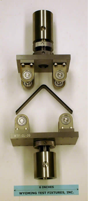
Fig. 1: Standard specimen show with test fixture and optional adapters.
This test method can be used to determine the interlaminar tensile strength of a unidirectional composite. ASTM D6415 (Reference 1) states that it is for use in determining the curved beam strength of a continuous fiber-reinforced composite material.
The curved beam specimen consists of two straight legs connected by a 90 degree bend with a 1/4” inner radius, as shown in Fig. 1. The standard specimen is 1” wide and can range from 0.1” to 0.5” thick depending on the material and laminate being tested. An out-of-plane (through-the-thickness) tensile stress is produced in the curved region of the specimen when a bending moment is developed in the specimen as the compressive load is applied.
A fixture without the optional adapters is shown in Fig. 2, with a thicker specimen installed. The specimen is supported and loaded by 3/8” diameter cylinders mounted in ball bearings. A 1”-14 UNF threaded hole is provided in both the top and bottom of the fixture, for attachment to the base and crosshead of the testing machine. Another view of the standard fixture is shown in in Fig. 3, to better indicate its size.
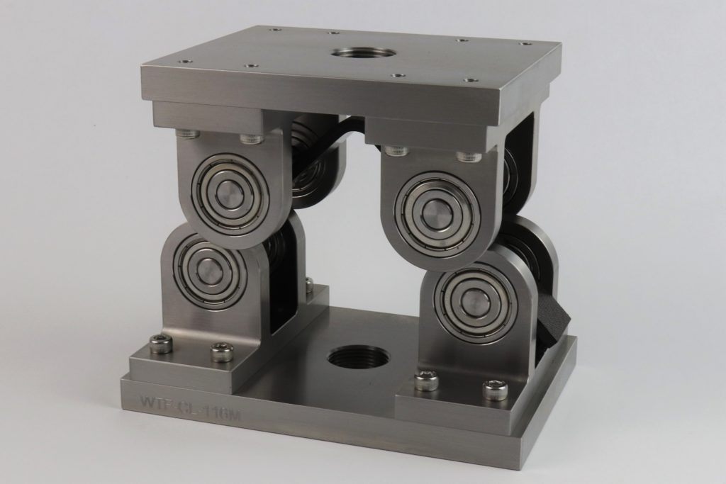
Fig. 2: Standard test fixture with specimen installed.
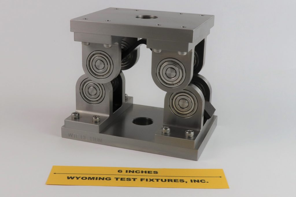
Fig. 3: Standard fixture shown with ruler for scale.
A compressive force is applied in displacement control until one or more delaminations form in the specimen, as indicated in Fig. 4, causing the applied force to drop. ASTM D6415 gives the equations required to calculate the specimen strength.
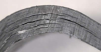
Fig. 4: Failed specimen
Fig. 5 shows a special Curved Beam Strength Test Fixture, designed with adjustable support and loading span lengths. Some standards other than ASTM specify other support and loading span lengths, and also other support and loading cylinder diameters. For example, Airbus AITM1-0069 (Reference 2) varies both span length and cylinder diameter as a function of specimen thickness, making an adjustable fixture almost mandatory.
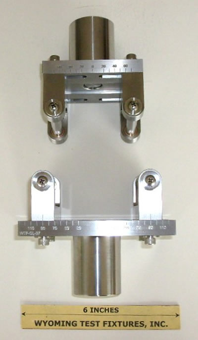
Fig. 5: Special Curved Beam Strength Test Fixture with adjustable specimen support and loading spans
Occasionally, extra-wide specimens are to be tested. Fig. 6 shows a fixture with adjustable specimen support and loading spans that is also capable of testing wide specimens.
Although not a standard, the Angle Bend Test Fixture has also been used. The fixture is shown in Fig. 7.
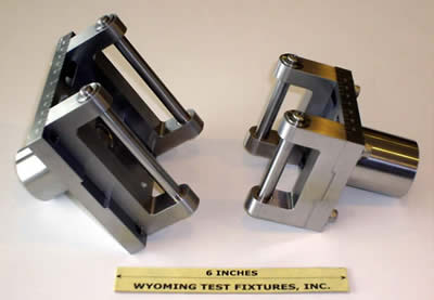
Fig. 6: Special wide-specimen fixture with adjustable loading and support spans.
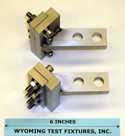
Fig. 7: Angle Bend Test Fixture
Each leg of the curved beam specimen is clamped in the fixture, which is then loaded in tension via the projecting arms, inducing a bending moment along with the tensile load.
Source of Additional Information:
1) ASTM Standard D6415-06 (2013), "Standard Test Method for Measuring the Curved Beam Strength of a fiber-Reinforced Polymer-Matrix Composite," American Society for Testing and Materials, West Conshohocken, Pennsylvania (first published in 1999).
2) AITM1-0069, Issue 2, "Determination of Curved-Beam Failure Load," Airbus S.A.S, Engineering Directorate, Blagnac, France, December 2011.
