Boeing Compression After Impact Test Fixture (ASTM D7137)
Model No. WTF-CI (Stainless Steel)
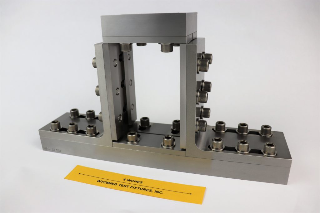
Fig. 1: Assembled Fixture without specimen installed.
This test method was adopted by ASTM as Standard D7137 (Reference 1) in May 2005. A companion standard, ASTM D7136 (Reference 2), defines the method of impacting the test specimen prior to performing the compression test.
This Compression After Impact (CAI) Compression Test Fixture was developed by the Boeing Company, as described in References 3 and 4. A slight fixture modification is described in SACMA Recommended Method SRM 2R-94 (Reference 5). The specimen, typically, but not necessarily, a quasi-isotropic laminate, is 6 in. long, 4 in. wide, and approximately 0.2 in. thick. A NASA standard fixture, described in Reference 6, specifies a larger specimen and thus is not as commonly used as the Boeing standard fixture.
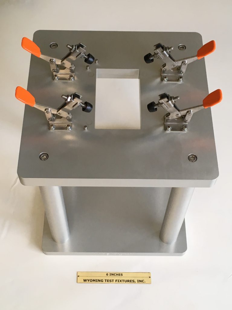
Fig. 2: Impact stand as described in ASTM D7136.
The Boeing test specimen is first impacted as defined in Reference 2, typically using a drop-weight impact testing apparatus as shown in figure 2. The impact stand can be purchased as model number WTF-IS.
The impacted specimen is then compression loaded to failure in the fixture shown in Fig. 1. The specimen is simply supported along all four edges, the fixture being adjustable, as indicated by the large number of socket head cap screws, to accommodate small variations in specimen width and thickness. The top (loading) plate, which is not directly attached to the lower portion of the fixture, slips over the top edge of the test specimen to provide simple support for this fourth edge. The side rails are short enough to insure that a gap between the side rails and the top plate is maintained during the compression test. The assembled fixture, with a specimen installed, is positioned unconstrained on the flat base of the testing machine, the compressive loading being applied directly to the top plate by a platen in the crosshead of the testing machine.
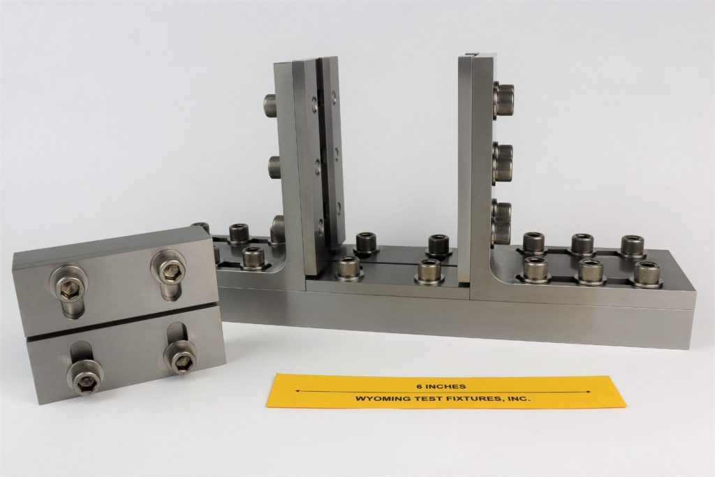
Fig 3: Partially assembled fixture with loading plate removed.
Because the laminate is quasi-isotropic or something similar, and thus does not have a high inherent compressive strength, and furthermore has been typically weakened by the prior impact loading, it can be edge-loaded without crushing, even though it is untabbed.
An Airbus Industries version of the Compression After Impact Compression Test Fixture is shown in Fig. 4, for comparison. More details are given in products section of this web site. Screws are provided to forcibly push the top, bottom, and side plates against the test specimen, providing a positive clamping force to all four sides of the specimen. However, the effective specimen boundary conditions are still “simply supported”, the same as for the Boeing fixture. The specimen is the same size as that used with the Boeing fixture. Although the fixture uprights are not adjustable in the width direction as they are in the Boeing fixture, this is not a problem as the standard specimen is specified to be of a specific size anyway.
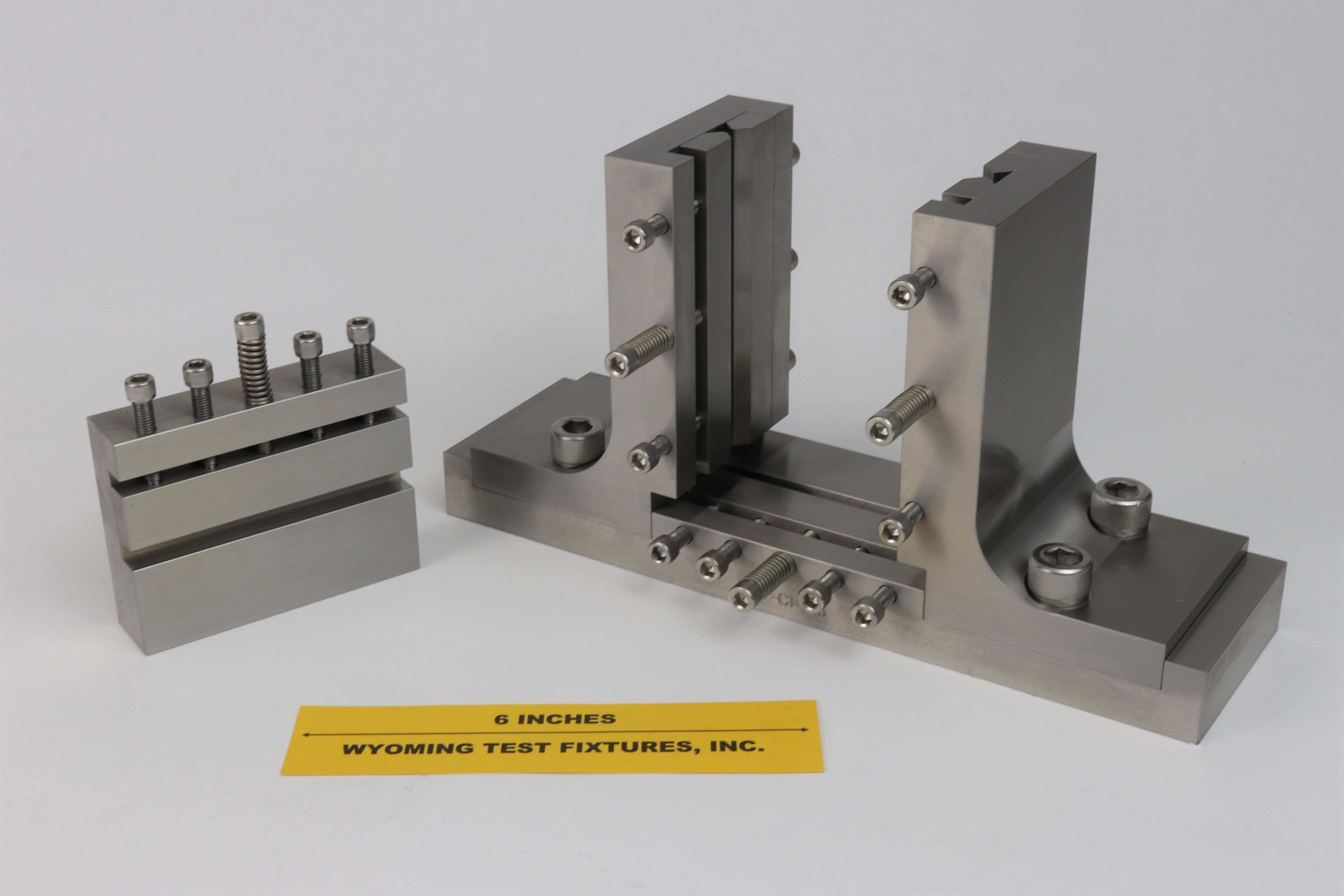
Fig. 4 Airbus Industries After-Impact Compression Test Fixture.
Special Compression After Impact Compression test fixtures can also be fabricated. Figure 5 shows one such example. In the foreground is a standard Boeing fixture. In the background is a specially designed fixture, capable of testing specimens either 6 in. or 10.5 in. tall and 4 in., 8.5 in., or 10.5 in. wide. Another special CAI fixture is shown in Figs. 6 and 7. This fixture is designed to test tall, narrow specimens.
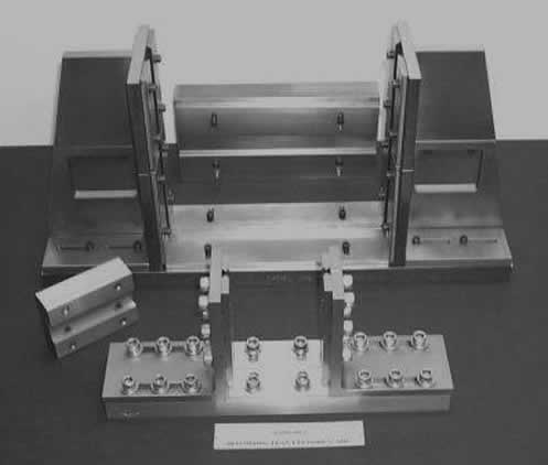
Fig 5: Special large-scale After-Impact Compression Test Fixture shown in the background with a standard size Boeing fixture in the foreground.
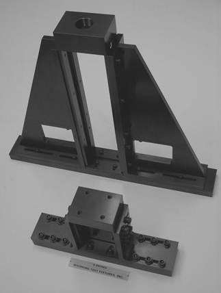
Fig 6: Another special large-scale After-Impact Compression Test Fixture in the background shown with a standard size Boeing fixture in the foreground.
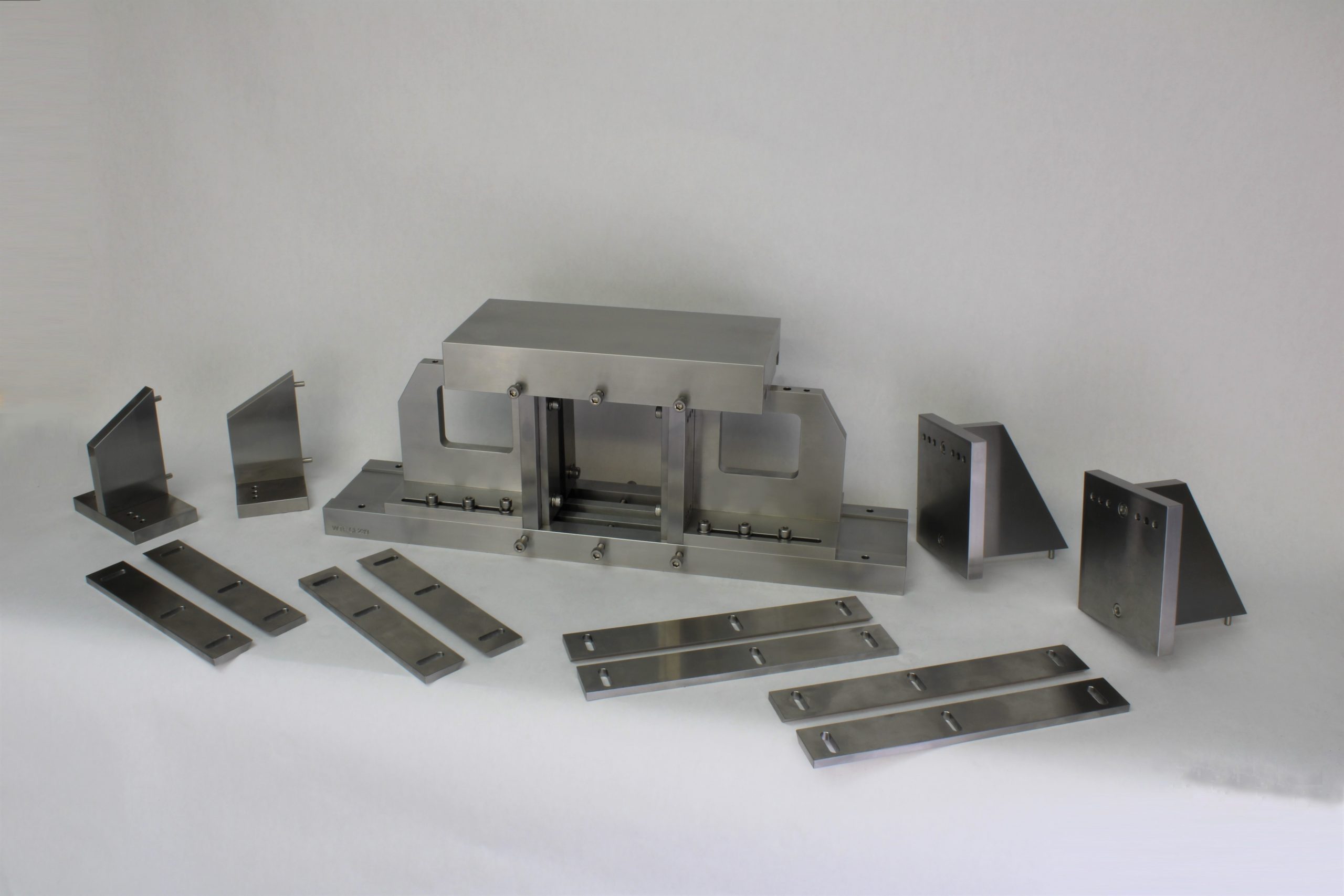
Fig 7: A special CAI fixture is shown in its smallest configuration with its additional component parts. This fixture is designed to test 4 x 6 in., 6 x 8.5 in., and 8.5 x 10.5 in. specimens, up to a maximum thickness of 1.25 in.
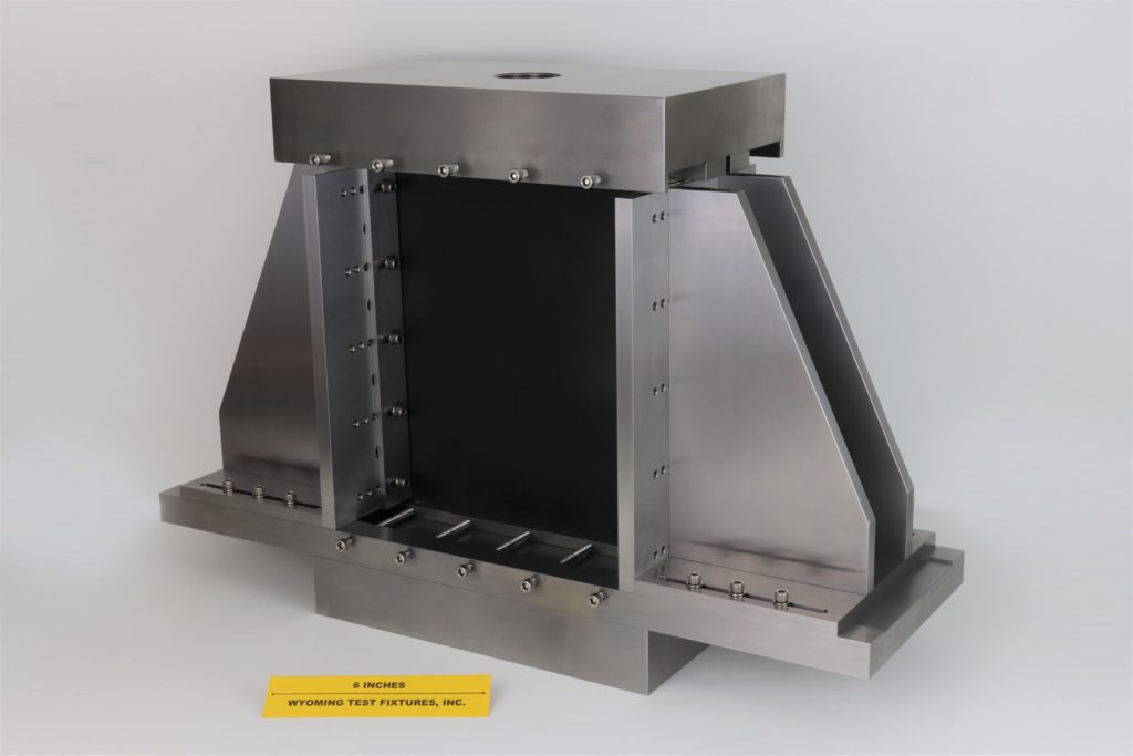
Fig. 8: Another large scale version of the CAI fixture
Sources of Additional Information:
1) ASTM Standard D7137-12 (2012), "Standard Test Method for Compression Residual Strength Properties of Damaged Polymer Matrix Composite Plates,” American Society for Testing and Materials, West Conshohocken, Pennsylvania (first issued in 2005).
2) ASTM Standard D7136-12 (2012), "Standard Test Method for Measuring the Damage Resistance of a Fiber-Reinforced Polymer Matrix Composite to a Dynamic Impact Event,” American Society for Testing and Materials, West Conshohocken, Pennsylvania (first issued in 2005).
3) Boeing Specification Support Standard BSS 7260, "Advanced Composite Compression Tests," The Boeing Company, Seattle, Washington (originally issued February 1982, revised December 1988).
4) Boeing Document D888-10026, "Test Methods for Advanced Composites, Revision A, Section 7.4, The Boeing Company, Seattle, Washington, January 1996.
5) SACMA Recommended Method SRM 2R-94, "Compression After Impact Properties of Oriented Fiber-Resin Composites," Suppliers of Advanced Composite Materials Association, Arlington, Virginia, 1994.
6) NASA Reference Publication 1092, "Standard Tests for Toughened Resin Composites," NASA-Langley Research Center, Hampton, Virginia, Revised Edition, July 1983.

