Iosipescu Shear Test Fixture (ASTM D5379)
Model No. WTF-IO (Stainless Steel)


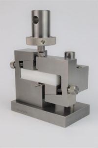
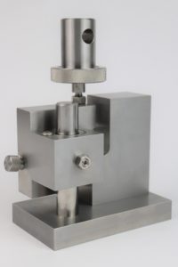
Fig. 1: ASTM Standard D5379 Iosipescu Shear Test Fixture, shown with Optional Adapter
The Iosipescu shear test fixture was actively developed for use with composite materials during the late 1970's and early 1980's by the Composite Materials Research Group at the University of Wyoming. A large number of fixtures have been provided to research groups around the world since that time and the test method is now in widespread use. ASTM Standard D5379 governing the test method was first issued in 1993 (Reference 1). General testing procedures are provided in that standard. In addition, considerable additional discussion of results typically obtained is contained in the references listed here.
The standard test specimen (as shown installed in the front view photograph of Fig. 1) is 3 in. long, 0.75 in. wide, and of any thickness up to 0.50 in. Typically, a specimen on the order of 0.1 in. thick is used. The fixture will also accommodate shorter and narrower specimens, if desired. A 90° notch is machined into each edge of the specimen, and a strain gage can be mounted on the specimen surface in the notched region to monitor shear strain. Either a standard ±45° biaxial gage or a special Iosipescu gage is commonly used. The small diameter rod projecting out of the fixture below the lower notch in the specimen (front view photograph in Fig. 1) is lifted up with a finger while installing a test specimen, to center the specimen left to right. The specimen is pushed up against the flat back of the fixture to locate it fore and aft. The tapered wedges are not intended to be clamps; they are adjusted with finger knobs to accommodate specimens of slightly varying widths. Wedges of alternate thickness can be provided to accommodate specimens outside this small range of thickness variation.
The moving half of the fixture incorporates a linear ball bushing (see rear view photograph in Fig. 1) that moves on a hardened steel vertical post mounted in the base of the fixture. This ball bearing eliminates guidepost binding and minimizes frictional resistance. The closeness of fit of the bearing can be adjusted via the screw and locking nut visible on the backside of the moving half of the fixture.
In use, the fixture rests unconstrained directly on the base of the testing machine. A standard 1.25 in. diameter stud with lock ring and 0.50 in. diameter cross-pin hole, threaded into the moving half of the fixture, is available for purchase with the fixture, as shown on the standard-size fixture in Fig. 2. Any special adapter required to attach this stud to the particular testing machine being used, such as the standard Instron Type Df adapter (Fig. 1), can be provided as an option at nominal additional cost. The adapter is pinned to the stud and secured via the lock ring provided with the fixture.
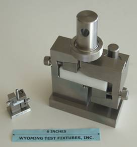
An example of a special fixture is shown in Fig. 2. The small fixture on the left is essentially a one-quarter scale model of the standard fixture, designed to test a specimen only 20 mm long, 5 mm wide, and up to 5 mm thick. A standard-size fixture is shown on the right for comparison. Special larger-than-standard fixtures have also been fabricated for customers.

Fig. 2: Quarter-Scale Iosipescu Shear Fixture (left) and Standard Fixture (right)
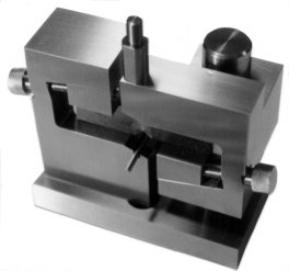
Fig. 3 shows a special fixture designed for high temperature testing. This fixture is fabricated of a nickel superalloy for use at temperatures up to 1500ºF (815ºC). Since ball bushings capable of operating at these high temperatures are not available, the right half of the fixture moves on a large diameter, close-fitting alignment post. Also, since this fixture is normally used in a high temperature furnace, the base of the fixture contains a threaded hole (barely visible) for attachment to a support column, and a threaded stud is provided at the top for attachment.

Fig. 3: Nickel Superalloy Iosipescu Shear Test Fixture for Use to 1500°F (815°C)
Sources of Additional Information:
1) ASTM Standard D5379-12, "Standard Test Method for Shear Properties of Composite Materials by the V-Notched Beam Method," American Society for Testing and Materials, West Conshohocken, Pennsylvania (first published in May 1993).
2) N. Iosipescu, "New Accurate Procedure for Single Shear Testing of Metals," Journal of Materials, Vol. 2, No. 3, September 1967, pp. 537-566.
3) D.E. Walrath and D.F. Adams, "The Iosipescu Shear Test as Applied to Composite Materials,"Experimental Mechanics, Vol. 23, No. 1, March 1983, pp. 105-110.
4) D.F. Adams and D.E. Walrath, "Current Status of the Iosipescu Shear Test Method," Journal of Composite Materials, Vol. 21, June 1987, pp. 484-505.
5) D.F. Adams and D.E. Walrath, "Further Development of the Iosipescu Shear Test Method,"Experimental Mechanics, Vol. 27, No. 2, June 1987, pp. 113-119.
6) D.F. Adams, "The Iosipescu Shear Test Method as Used for Testing Polymers and Composite Materials," Polymer Composites, Vol. 11, No. 5, October 1990, pp. 286-290.
7) D.F. Adams and E.Q. Lewis, "Experimental Strain Analysis of the Iosipescu Shear Test Specimen," Experimental Mechanics, Vol. 35, No. 4, December 1995, pp. 352-360.

