Wyoming Modified Celanese Compression Test Fixture
Model No. WTF-WC (Stainless Steel)

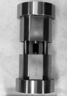
Fig. 1: Assembled Wyoming Modified Celanese Compression Test Fixture.
The Wyoming Modified Celanese Compression Test Fixture represents a design improvement relative to the now withdrawn ASTM Standard D 3410 Celanese Compression Test Fixture (Reference 1). The standard Celanese fixture is frequently criticized because of its cone-in-cone arrangement of the wedge grips. In order to maintain full surface contact between each pair of split half-cones gripping a tabbed specimen end and the mating cone cavity in the end block, the tabbed ends of the specimen must be fabricated to a precise thickness. This increases specimen preparation time and cost significantly, and reduces the reliability of the test method.
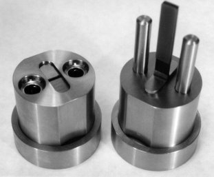
The Wyoming Modified Celanese Compression Test Fixture was developed at the University of Wyoming (References 2 through 4). As indicated in Fig. 2, which shows the fixture halves separated, the fixture incorporates tapered circular cylindrical wedges, which thus remain in full surface contact with the tapered circular cylindrical cutouts of the same radius in the end blocks, independent of specimen thickness. This eliminates the major criticism of the standard Celanese test fixture. On the other hand, the overall circular geometry of the Celanese fixture, which is very efficient in sustaining the high circumferential (hoop) stresses developed in the end blocks during a compression test, has been retained. Thus, the fixture is very compact relative to the IITRI and Wyoming Modified IITRI compression test fixtures, weighing only about 10 lb.

Fig. 2: Fixture halves separated, specimen partially installed
Alignment rods in linear bearings are used, as in the IITRI and Wyoming Modified IITRI test fixtures, rather than an external alignment sleeve as in the standard Celanese fixture. This minimizes friction and potential binding, improves alignment, and provides greater access to the gage region of the test specimen for instrumentation and observation.
Screws threaded into each of the wedges at their outer ends are provided to permit tightening of the wedges on the specimen during installation. This initial gripping of the specimen prevents it from slipping in the grips when the testing machine loading is first applied. These screws do not have to be extremely tight since, as the testing machine loading is increased, the wedge action of the grips due to this loading becomes dominant.
The fixture is designed to test a specimen nominally 4.5 in. long and 0.50 in. wide, although a narrower specimen can be tested, if desired. For example, the fixture can accommodate a standard 0.25 in. wide Celanese specimen, if the standard Celanese specimen length of 5.5 in. is reduced to 4.5 in. The standard gage length is 0.50 in., the same as for the IITRI, Wyoming Modified IITRI, and Celanese test fixtures. The overall specimen length is 1" less than for the other fixtures, all of which have a 10º wedge taper angle. This reduced grip length is compensated for by decreasing the wedge taper angle to 8º.
The Wyoming Modified Celanese fixture is designed to accommodate specimen thicknesses in the tab regions in the range of 0.15 in. to 0.25 in..
The standard gage length (the distance between the tabs) for all compression test fixture configurations following the general guidelines of ASTM Standard D3410 is 0.50 in. Thus, the tab length for standard specimens used with the Wyoming Modified Celanese Compression Test Fixture is 2". The fixture can be used to test nonstandard gage length specimens also, from zero to approximately 1 in. (If longer alignment rods are substituted, specimens of longer gage lengths can be used.)
Serrated grip faces are supplied as standard. However, tungsten carbide particle-coated grip faces are also available.
Sources of Additional Information:
1) ASTM Standard D3410-03 (reapproved 2008), "Compressive Properties of Polymer Matrix Composite Materials with Unsupported Gage Section by Shear Loading," American Society for Testing and Materials, West Conshohocken, Pennsylvania (first published in 1975).
2) M.N. Irion and D.F. Adams, "Compression Creep Testing of Unidirectional Composite Materials,"Composites, Vol. 2, No. 2, April 1981, pp. 117-123.
3) J.S. Berg and D.F. Adams, "An Evaluation of Composite Material Compression Test Methods,"Journal of Composites Technology and Research, Vol 11, No. 2, Summer 1989, pp 41-46.
4) D.F. Adams and E.M. Odom, "Influence of Test Fixture Configuration on the Measured Compressive Strength of a Composite Material," Journal of Composites Technology and Research, Vol. 13, No. 1, Spring 1991, pp. 36-40.

