Wyoming Combined Loading Compression Test Fixture (ASTM D6641)
Model No. WTF-EL (Stainless Steel)
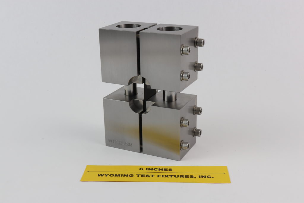
Fig. 1: Assembled Wyoming Combined Loading Compression Test Fixture with specimen installed.
The Wyoming Combined Loading Compression (CLC) Test Fixture, originally developed at the University of Wyoming (References 1 through 3), became ASTM Standard D6641 in 2001 (Reference 4).
The CLC fixture consists of two pairs of steel blocks, each pair being clamped together with four bolts, as indicated in Fig. 1. When installed, the ends of the 5.5 in. long specimen are flush with the ends of the blocks. The 1.2 in. wide gripping surfaces of the blocks are intended for testing specimens up to nominally 1 in. wide.
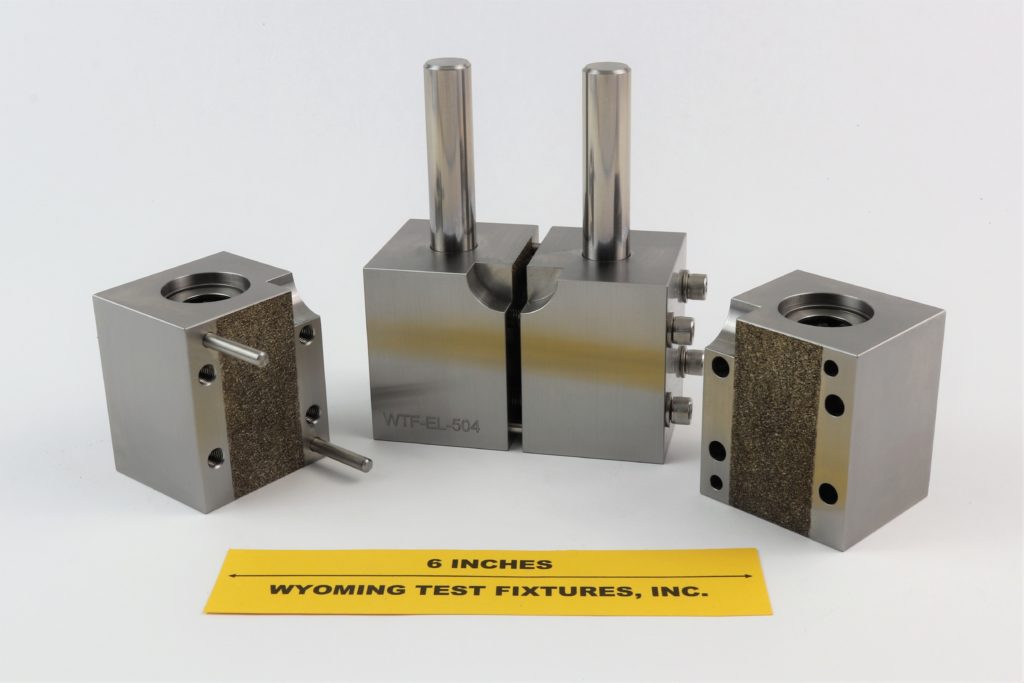
Fig. 2: Partially disassembled fixture showing the tungsten carbide particle-coated gripping surfaces.
These gripping surfaces are coated with tungsten carbide particles, as shown in Fig. 2, to enhance the frictional force and thus permit higher shear load transfer into the specimen. And since these surfaces are relatively smooth (100 grit particles), they do not damage the surface of the specimen. This permits the use of untabbed specimens in many applications, a major advantage in terms of specimen fabrication cost.
By adjusting the bolt torque, the ratio of end- to shear-loading of the specimen can be controlled, i.e., combined loading can be achieved. This permits the successful testing of stronger materials than if the specimen was purely end-loaded (by avoiding end crushing), and less clamping force than if the specimen was purely shear-loaded (lower clamping-induced stress concentrations).
The fixture blocks also prevent gross buckling of the specimen. Two alignment rods in linear bearings are used to keep the upper and lower pairs of blocks aligned, the linear bearings eliminating frictional binding of the alignment rods. The circular recess shown in one face provides clearance for an edge-mounted extensometer, if used. Alternatively, bonded strain gages can be used on one or both faces of the specimen.
The assembled fixture, with a specimen installed, is placed unconstrained on a flat base of the testing machine, and loaded directly on its top face by a flat platen mounted in the crosshead of the testing machine.
The Wyoming Combined Loading Compression (CLC) Test Fixture is designed to accommodate tabbed or untabbed specimens 5.5 in. long. This is the same length as commonly used with the IITRI tabbed specimen test method (ASTM D3410). The gage length (the distance between the restraining end blocks), at 0.50 in. is also the same. The CLC fixture can be used to test nonstandard gage length specimens by simply altering the specimen total length. This fixture is relatively compact, weighing 10.6 lb.
The CLC test method has been shown to be totally suitable for compression testing untabbed specimens of materials of moderate strengths, e.g., composites exhibiting compressive strengths up to about 150 ksi, which includes cross-ply and quasi-isotropic lay-up laminates, fabric composites, random chopped-fiber composites, and other materials of similar or lower strength. In such cases the CLC test fixture has been shown to produce compressive strength and modulus values fully equivalent to those obtained using tabbed specimens and more complex and expensive test fixtures such as the IITRI, Wyoming Modified IITRI, Celanese, and Wyoming Modified Celanese configurations (References 1 through 3).
Non-standard fixtures can also be designed and fabricated. For example, Fig. 3 compares the standard fixture (left) with a fixture designed to accommodate specimens of the same 5.5 in. length but up to 2.5 in. wide.
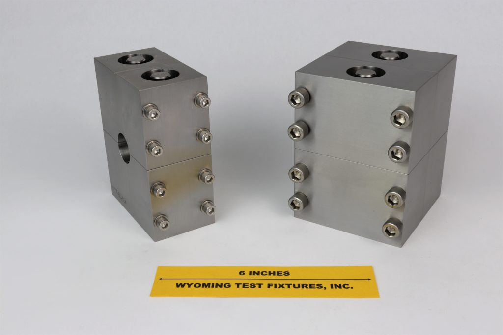
Fig. 3: ASTM D 6641 Standard Fixture (left) and Special 2.5” Specimen Width Fixture (right).
Fig. 4 shows a reduced-size fixture, designed to test specimens only 2.5 in. long and up to 0.5 in. wide, with a standard fixture in the background for comparison.
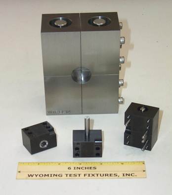
Fig. 4: Special reduced-size fixture shown (disassembled) in the foreground, with a standard fixture in the background.
Three different size CLC fixtures are shown in Fig. 5, as examples of size variations sometimes used. We have designed and fabricated even larger and smaller CLC fixtures.
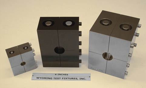
Fig. 5: Three different size combined loading compression test fixtures, the standard size fixture shown in the center.
A special CLC fixture, with four alignment rods and linear bearings, is shown partially disassembled at the left of Fig. 6. A partially disassembled standard fixture is shown at the right. With increasing interest in the use of Digital Image Correlation (DIC) techinques to obtain full-field displacements of the surface of the test specimen, it is necessary for the instrumentation to be able to view the face of the test specimen. The two alignment rods of the standard fixture block this view. By using four alignment rods, a line of sight is available between the pairs of rods, while maintaining the fixture symmetry.
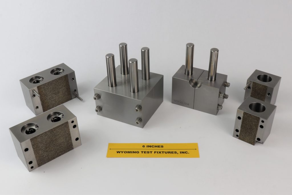
Fig. 6: A Special Combined Loading Compression (CLC) Test Fixture with four alignment rods is shown at the left with a standard fixture to the right.
Another view of the special fixture with four alignment rods of Fig. 6 is shown fully disassembled in the forground of Fig. 7, along with the spacer strips and a pusher strip for installing 1/2 in. and 1 in. wide specimens. A completely assembled fixture is shown in the background along with a standard fixture. This special fixture weighs 20 lb, approximately twice that of the standard fixture, and can accommodate specimens up to 2.5 in. wide, if desired. The clear space between alignment rods is slightly more than 1.2 in.
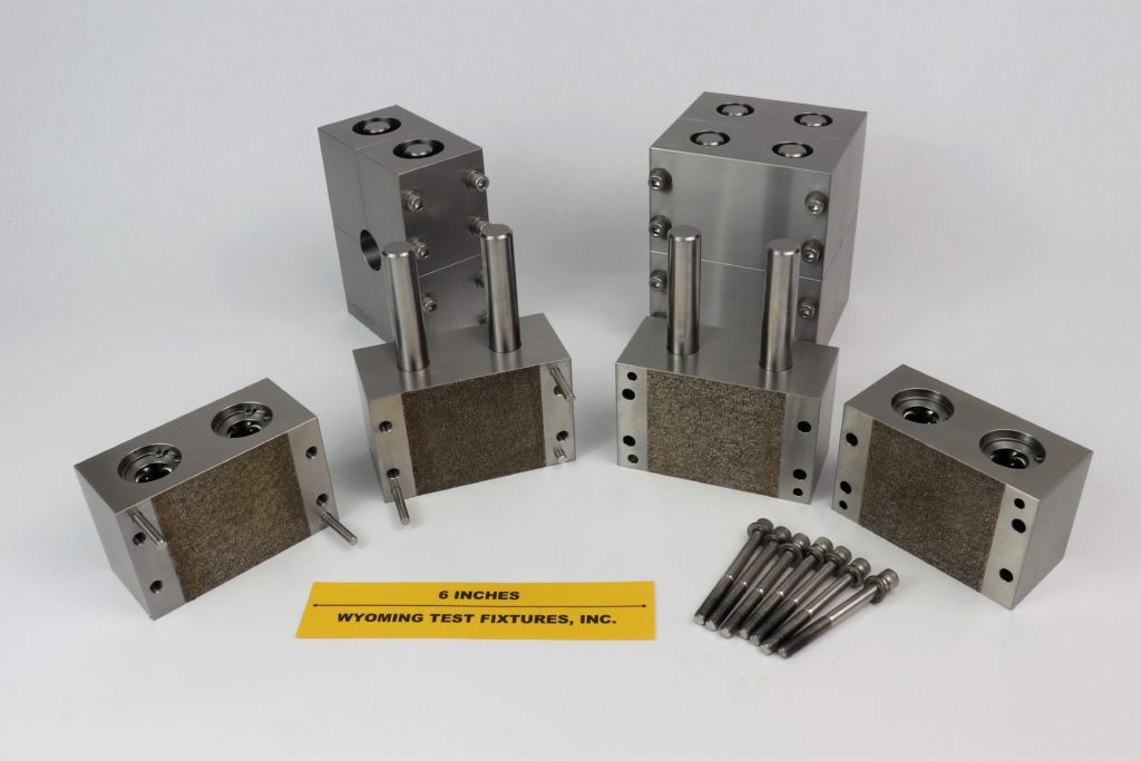
Fig. 7: The Special Four-Alignment Rod CLC Fixture is shown completely disassembled in the foreground. An assembled fixture and a standard fixture are shown in the background.
The tungsten carbide particle grip surfaces of any of the above fixtures will eventually show wear after long term use (typically many hundreds of specimen tests), and may have to be recoated. As wear progresses, higher and higher bolt torques will be required to achieve equivalent results. An extreme example of surface wear is shown in Fig. 8. Normally use of the fixture is not continued to this point. The original coating can be ground off and the fixture recoated, restoring the fixture to its original condition.
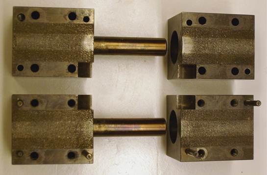
Fig. 8: Example of a well-used standard size Combined Loading Compression Test Fixture. The wear pattern of the tungsten carbide particle grip surfaces caused by a ½ in. wide specimen can be seen, with excessive wear at the ends near the specimen gage section.
Sources of Additional Information:
1) D.F. Adams and J.S. Welsh, "The Wyoming Combined Loading Compression (CLC) Test Method,"Journal of Composites Technology and Research, Vol. 19, No. 3, 1997, pp. 123-133.
2) P.M. Wegner and D.F. Adams, "Verification of the Combined Load Compression (CLC) Test Method," Report No. DOT/FAA/AR-00/26, Federal Aviation Administration Technical Center, Atlantic City, New Jersey, August 2000.
3) J.S. Welsh and D.F. Adams, “Current Status of Compression Test Methods for Composite Materials,” SAMPE Journal, Vol. 33, No. 1, January 1997, pp. 35-43.
4) ASTM Standard D6641-09 (2009), “Test Method for Determining the Compressive Properties of Polymer Matrix Composite Laminates Using a Combined Loading Compression (CLC) Test Fixture,” American Society for Testing and Materials, West Conshohocken, Pennsylvania (first issued in 2001).
5) D.F. Adams and G.A. Finley, “Experimental Study of Thickness-Tapered Unidirectional Composite Compression Specimens,” Experimental Mechanics, Vol 36, No. 4, December 1996, pp. 348-355.
6) S.L. Coguill and D.F. Adams, “Use of the Wyoming Combined Loading Compression (CLC) Fixture to Test Unidirectional Composites,” Proceedings of the 44th International SAMPE Symposium, Long Beach, California, May 1999, pp. 2322-2331.

