Modified ASTM D695 Compression Test Fixture (Boeing BSS 7260)
Model No. WTF-BO (Stainless Steel)
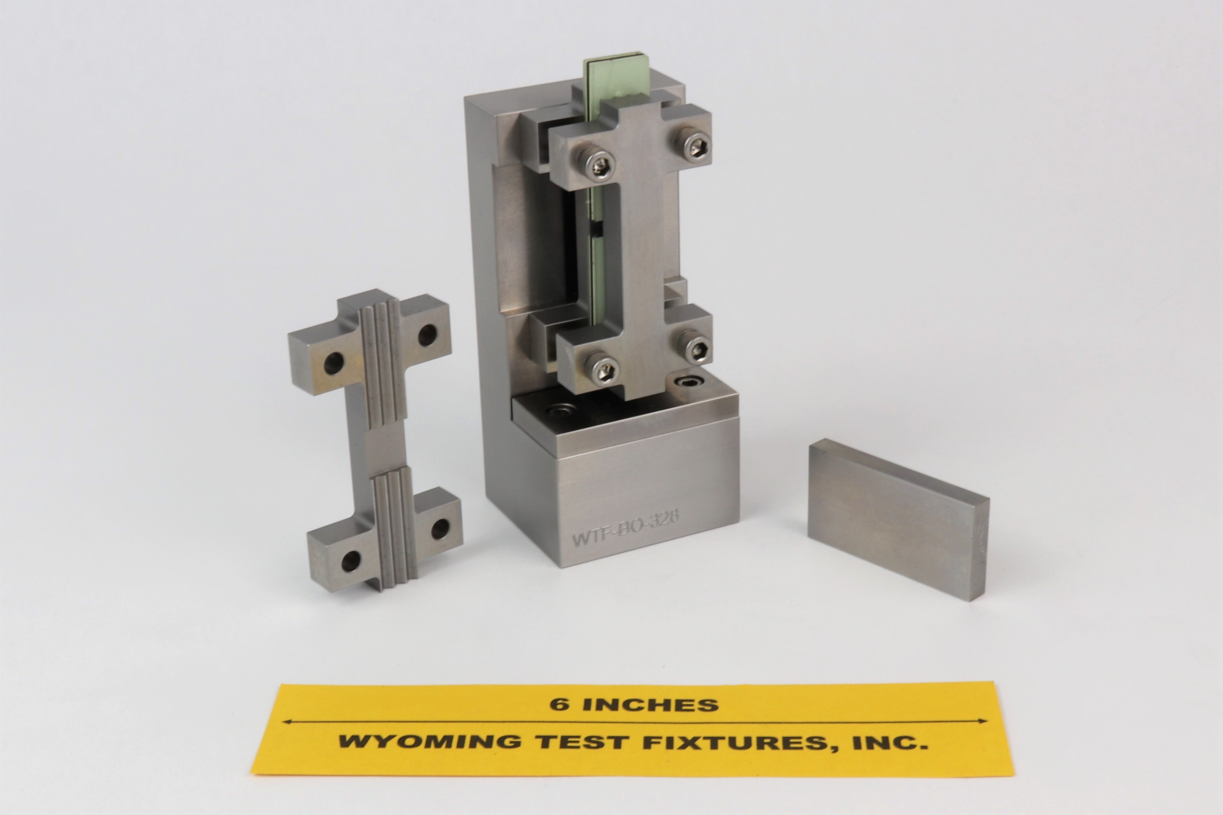
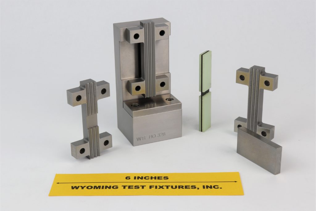
Fig. 1: Modified D695 Compression Test Fixture
This fixture is used to test composite materials in uniaxial compression. The flat piece shown in the left photograph of Fig. 1 is a hardened steel loading plate, to be placed between the protruding top end of the test specimen and the flat loading platen of the testing machine, to protect the loading platen.
There is actually no ASTM standard governing the Modified D695 Compression Test Method. ASTM Standard D695, originally published in 1942, is intended primarily for unreinforced plastics, as its title implies (Reference 1), using an untabbed, dog-boned, flat specimen. The Modified D695 Compression Test Method is defined in Boeing documents (References 2 and 3), and in SACMA Recommended Test Method SRM 1R-94 (Reference 4).
Although not an ASTM standard, this test method is used widely within the composite materials community at the present time, with reasonable success (References 5 through 7).
The straight-sided test specimen is 3.18 in. long and 0.5 in. wide and the thickness depends upon the material being tested. For a unidirectional composite, a thickness on the order of 0.040 in. is typically used. Specimens used to determine compressive strength are tabbed on each end, typically with glass fabric/epoxy tabbing material. The distance between tabs (the gage length) is specified to be 0.188 in. Because of this very short gage length, it is impractical to mount instrumentation to measure strains. Thus, two tests are specified.
A specimen without tabs is loaded to a minimum strain of 0.3 percent, using either a strain gage or an extensometer to measure strain. This permits the calculation of a compressive modulus. A second specimen of the same material, but with tabs, is then tested to failure, to determine the compressive strength. If it were attempted to load the untabbed specimen to ultimate, the specimen ends would typically crush before the material failed in a region away from the ends. Thus, a true compressive strength for the material would not be obtained.
To accommodate these two required tests, the fixture is provided with two outside support plates (the I-shaped pieces shown in the right photograph of Fig. 1), in addition to the inside support plate shown mounted on the fixture base. The grooves in the pieces used for the strength determination (the pieces shown mounted in the assembled fixture in the left photograph of Fig. 1) run the full length. A second outside support plate (shown lying in the foreground in the left photograph) is also provided, in which the grooves are relieved over the 0.5 in. central section, to provide clearance for a strain gage and its lead wires on one surface of the test specimen. When measuring strains, an untabbed specimen is used; a tabbed specimen of 0.188 in. gage length does not provide adequate space to mount a strain gage.
As an option, a fourth lateral support, also with the grooves relieved over its 0.5 in. central section, can be provided, so that strain gages can be mounted on both surfaces of the test specimen. However, dual strain gages are normally only used when specimen buckling is a concern. When determining compressive modulus, high stresses do not have to be applied, minimizing the problem of buckling.
The lateral support pieces and the bearing plates are actually fabricated of hardened 440C stainless steel. This minimizes the chance of them being permanently deformed (and thus rendered nonfunctional) when the specimen fails, often in a relatively violent compressive crushing mode.
Another option is a Specimen Indexing Accessory, as shown in Fig. 2 below. This Indexing Accessory is used to center the specimen between the lateral supports. As indicated, it screws into the side of the standard fixture.
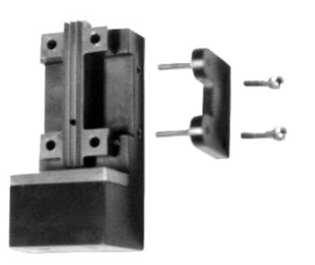
Fig. 2: Specimen indexing accessory for the Modified D695 Compression Test Fixture.
Special fixture configurations have also been designed and fabricated for customers. For example, Fig. 3 shows a special fixture designed to test a full size specimen but fit inside the close confines of a tube furnace. This particular fixture is fabricated of Inconel 718 nickel superalloy and has a slotted front cover plate for access to the specimen surface by an optical extensometer.
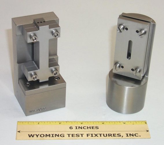
Fig. 3: Standard Modified D695 Fixture at left, special high temperature fixture at right.
Fig. 4 compares the SACMA SRM 1R-94 fixture with the standard Modified D695 fixture. The SACMA fixture is heavier, but tests the same size specimen in the same manner.
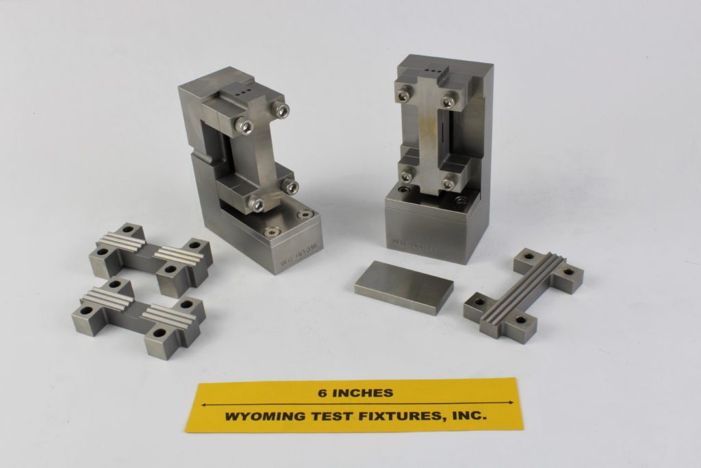
Fig. 4: SACMA SRM 1R-94 fixture on left, standard modified D695 fixture on right.
International standards are also becoming more predominant within the global testing community. Most of these standards are minor modifications of the ASTM standards, with slightly different fixture dimensions, and expressed in S.I. units. The fixture shown at the left in Fig. 5 is a typical example. Its functioning principles are the same as that of the Boeing-Modified D695 fixture shown at the right, although the longer base and thicker lateral supports make it look different.
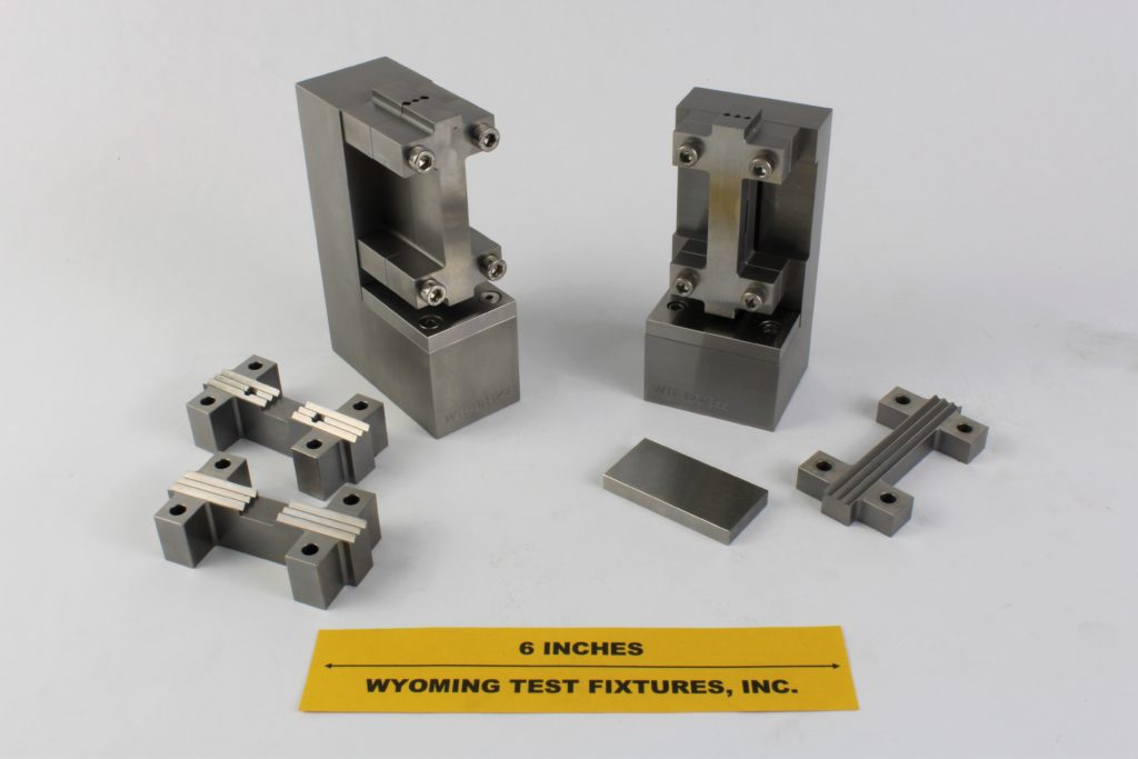
Fig. 5: European Standard prEN2850 End-Loaded Compression Test Fixture (left), compared to Boeing-Modified D695 Compression Test Fixture (right).
Sources of Additional Information:
1) ASTM Standard D695-10 (2010), "Compressive Properties of Rigid Plastics," American Society for Testing and Materials, West Cohshohocken, Pennsylvania (first issued in 1942).
2) Boeing Specification Support Standard BSS 7260, "Advanced Composite Compression Tests", The Boeing Company, Seattle, Washington (originally issued February 1982, revised December 1988).
3) Boeing Document D888-10026, "Test Methods for Advanced Composites, Revision A, Section C.2, The Boeing Company, Seattle, Washington, January 1996.
4) SACMA Recommended Method SRM 1R-94, "Compressive Properties of Oriented Fiber-Resin Composites," Suppliers of Advanced Composite Materials Association, Arlington, Virginia, 1994.
5) D.F. Adams and E.Q. Lewis, "Influence of Specimen Gage Length and Loading Method on the Axial Compressive Strength of a Unidirectional Composite Material," Experimental Mechanics, Vol. 31, No. 2, March 1991, pp. 14-20.
6) D.F. Adams, "Current Status of Compression Testing of Composite Materials," Proceedings of the 40th International SAMPE Symposium, May 1995, pp. 1831-1843.
7) J.S. Welsh and D.F. Adams, "Current Status of Compression Test Methods for Composite Materials," SAMPE Journal, Vol. 33, No. 1, January 1997, pp. 35-43.

