Compression Subpress (ASTM D695)
Model No. WTF-SP (Stainless Steel)
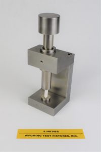
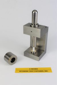
Fig. 1: Compression Subpress – 1 in. diameter
ASTM Standard D695 defines the testing of a laterally supported, thin, flat specimen configuration, the required fixture being Model WTF-BO (as described in Section B-2). In addition, the compression testing of an unsupported cylindrical specimen of round or square cross section is described in this same ASTM standard. In this case, the use of a subpress is recommended, to insure that the loading is applied axially and that the loading surfaces are flat and parallel.
Model WTF-SP satisfies the demanding tolerance requirements of ASTM Standard D695. It incorporates a hardened steel loading head and support anvil, and a spherical cap engaging a hardened steel loading rod which moves in a linear guide bearing. The spherical cap aids in preventing loading eccentricities from being induced by an improperly aligned testing machine.
The standard unit, shown in Fig. 1, can accommodate specimens up to 1 in. in diameter and 3.5 in. long. The "preferred" ASTM Standard D695 specimen size of 0.5 in. diameter (or 0.5 in. square) and 1 in. long (ultimate strength) or 2 in. long (modulus or offset yield stress) is thus well within this range.
Subpresses to accommodate specimens of larger sizes or special configurations can also be designed and fabricated. For example, both 1 in. and 2 in. diameter subpresses are shown in Fig. 2., a ½ in. diameter model is also sometimes used.
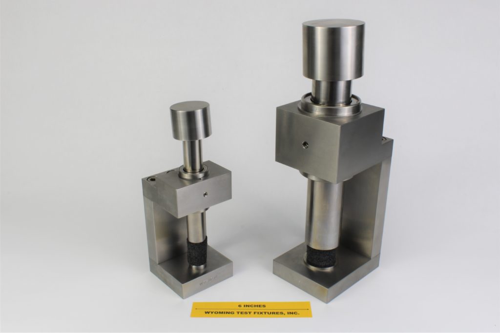
Fig. 2: 1 in. diameter (left) and 2 in. diameter (right) Compression Subpresses.
Another use of compression subpresses is to help ensure that a separate test fixture being used to apply a compressive load to a specimen is applying that loading axially. Such an application is shown in Fig. 3. A Modified D695 Compression Test Fixture (see Section B-2) is shown mounted in a 2" diameter compression subpress. The top end of the test specimen projects above the Modified D695 fixture when clamped in position between the two I-shaped lateral support plates. Thus, it is end-loaded by whatever device is used to apply the force. If the specimen is loaded directly by the platens of the testing machine, the uniformity of loading is dependent upon the alignment of the testing machine and platens. By mounting the Modified D695 fixture in a compression subpress, which in turn is mounted in the testing machine, the adverse influence of testing machine misalignments is eliminated.
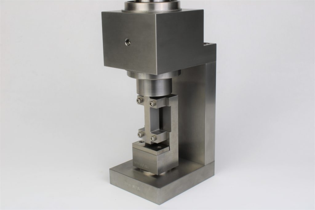
Fig. 3: Modified D695 Compression Test Fixture mounted in a 2 in. diameter Compression Subpress.
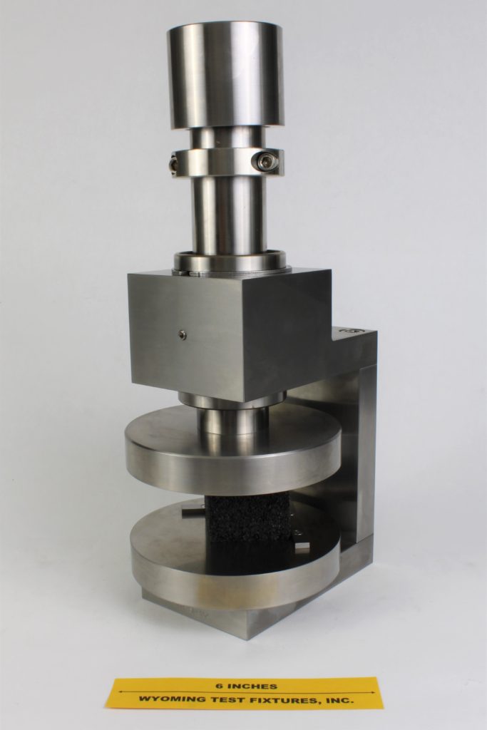
Fig. 4: Custom 2 in. diameter compression subpress with 6 in. diameter platens attached.
Source of Additional Information:
1) ASTM Standard D695-10 (2010), "Compressive Properties of Rigid Plastics," American Society for Testing and Materials, West Conshohocken, Pennsylvania (first issued in 1942).

