V-Notched Rail Shear Test Fixture (ASTM D7078)
Model No. WTF-NR (Stainless Steel)
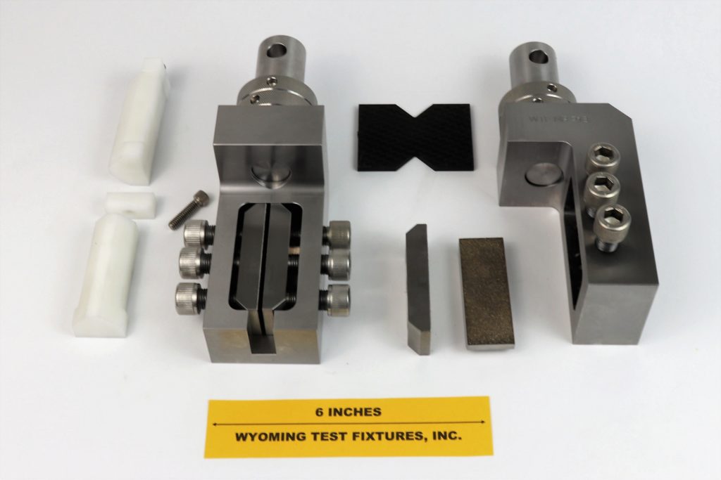
Fig. 1: V-Notched Rail Shear Test Fixture with a Standard V-Notched Specimen (top center).
The ASTM D7078 standard V-Notched Rail Shear specimen is 3.0 in. long (the same as the standard Iosipescu specimen), but 2.20 in. wide (versus 0.75 in. for the standard ASTM D5379 Iosipescu specimen), resulting in a much larger gage section between the notches (1.20 in. wide versus 0.45 in.). The specimen notch depth-to-width ratio of 0.227 is similar to the 0.200 ratio for the standard Iosipescu specimen, thus preserving the gage section geometry.
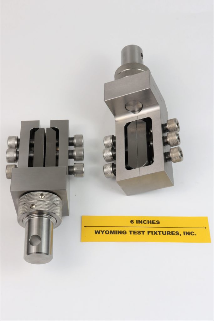
Fig. 2: V-Notched Rail Shear Test Fixture (ASTM D7078).
A 1.0 in. length along each end of the specimen is gripped by the test fixture. That is, the specimen is gripped up to the notches, resulting in a 1.0 in. ungripped region of the specimen being exposed between the grips. The fixture is supplied with threaded holes in each half of the test fixture for connecting to the test machine. Optional adapters, such as the standard 1.25 in. diameter stud with 0.50 in. diameter cross-pin hole (Instron Type Dm) shown in Fig. 1-3, can be supplied to mate with the customer’s testing machine.
A cutout is shown in the lower grip assembly at the left in both Figs. 1 and 2. This cutout permits specimen installation without having to remove the fixture from the testing machine, which is sometimes desirable, e.g., when performing elevated temperature or cryogenic testing.
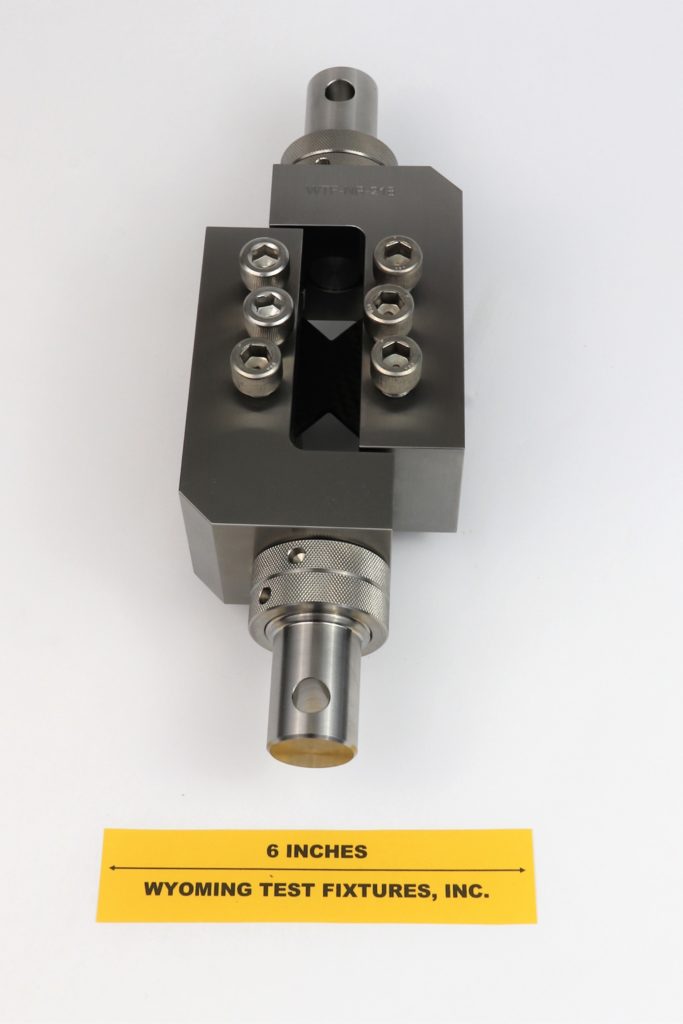
Fig. 3: Assembled V-Notched Rail Shear Test Fixture.
A pair of specimen installation spacers (jigs), shown in Fig 4, are provided with each fixture. These jigs are also shown at the extreme left in Fig. 1. These installation jigs are used to aid in centering the specimen notches between the rails during installation, and have been found to be very helpful by users of this test fixture. After specimen installation has been completed, the installation jigs are removed.
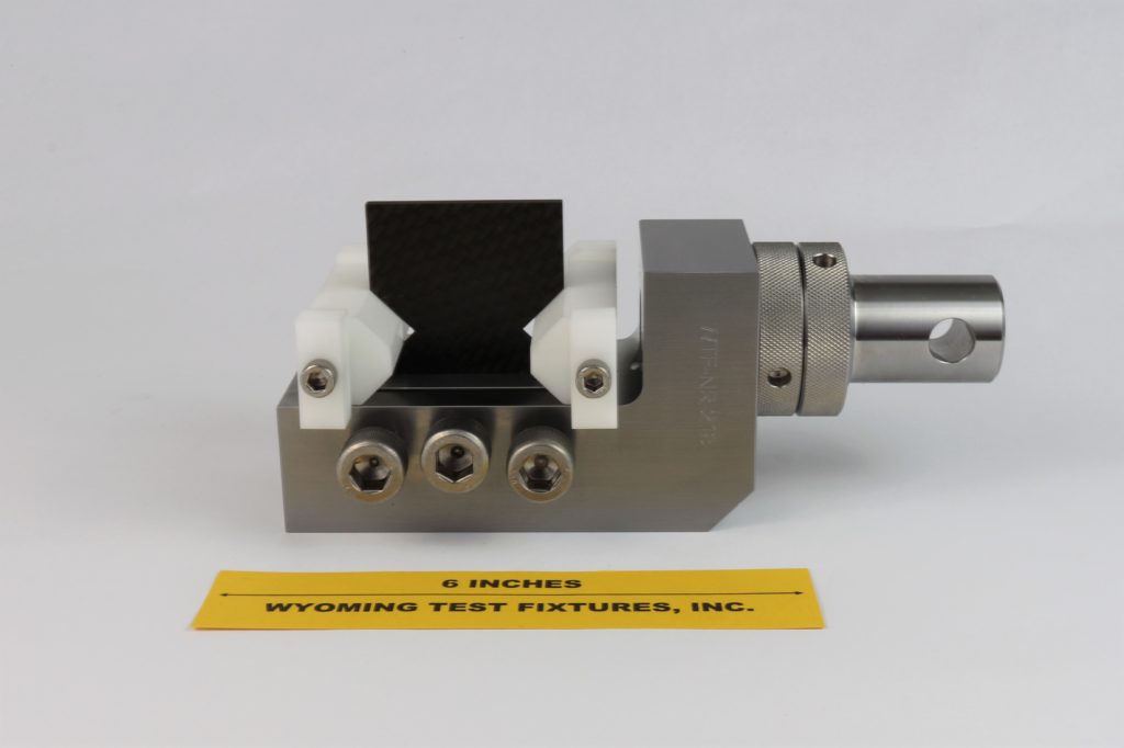
Fig. 4: Use of installation spacers (jigs) used to center the specimen.
Special configuration V-Notched Rail Shear fixtures can also be designed and fabricated. Fig. 5 shows a specially designed, adjustable gage-section width fixture. Nonadjustable fixtures for non-standard (fixed) gage section widths can also be fabricated.
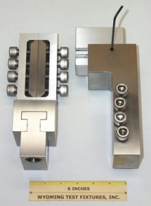
Fig. 5: Special Adjustable Gage-Section Width Test Fixture for testing specimens of variable (increased) gage-section width.
A Combined-Loading V-Notched Rail Shear Test Fixture, shown in Fig. 6, was produced by machining the height of the specimen cavity to be the same as the specimen width (2.20 in.). The depth of the cavity in each fixture half is also increased to 2.0 in. and the length of the V-notched specimen is increased from 3.0 in. to 5.0 in. When the specimen is loaded and attempts to slip and thus rotate in the fixture, the edges of the specimen will become loaded, just as for the standard ASTM D5379 Iosipescu shear test specimen. That is, a combined edge and face loading of the specimen is achieved, i.e., Combined Loading Shear (CLS). Note also that the fixture body is much heavier, and four larger diameter screws are used on each side compared to the three screws in the standard fixture. The disadvantage of this fixture design is that the specimen width must be machined accurately so that there will be a close fit between it and the fixture opening.
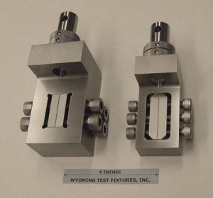
Fig. 6: Combined Loading Shear (CLS) test fixture (left) shown with the standard V-Notched Rail Shear Test Fixture (right).
As an alternative, an Adjustable Combined Loading V-Notched Rail Shear test fixture has been developed. This fixture is shown in comparison to the standard V-Notched Rail Shear Test Fixture in Fig 7. Note that the depth of the cavity in which the specimen is gripped has been increased from 1 in. to 2 in. in the Combined Loading Shear test fixture (left) to provide greater surface area and edge distance for specimen loading. Whereas the standard V-Notched Rail Shear specimen is 3 in. x 2.2 in. as shown above in Fig. 5, the Combined Loading Shear specimen is 5 in. x 2.2 in. However, the size and shape of the central notched test section of the specimen is the same for the two test configurations.
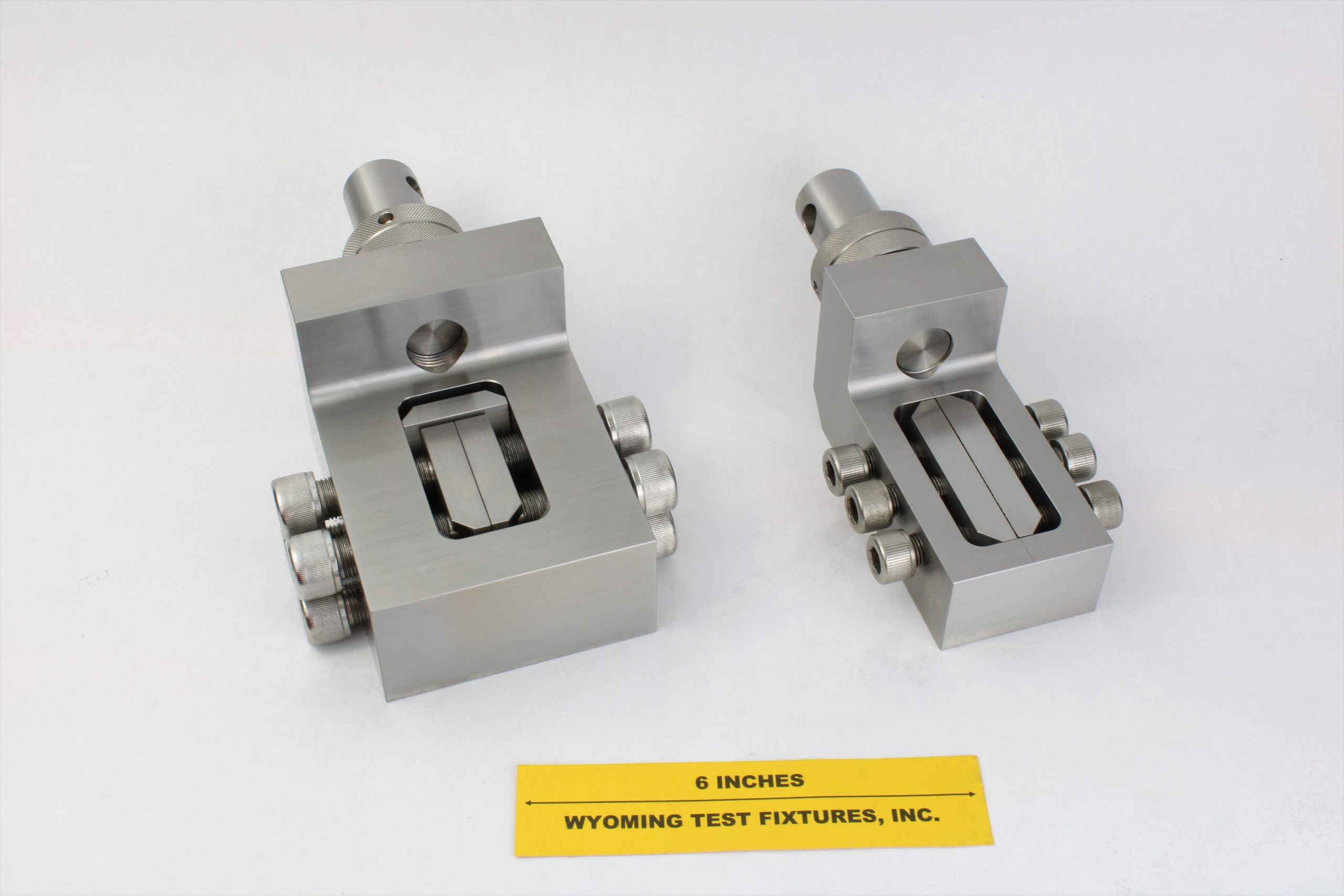
Fig. 7: Adjustable Combined Loading Shear (CLS) Test Fixture (left) shown with the standard V-Notched Rail Shear Test Fixture (right).
The adjustable Combined Loading Shear test fixture is shown partially disassembled in Fig. 8. A flat plate contacts the edge of the specimen, being held against the specimen by a screw. This screw can be used to adjust for the width of the specimen, or to actually apply a preload to the specimen edges.
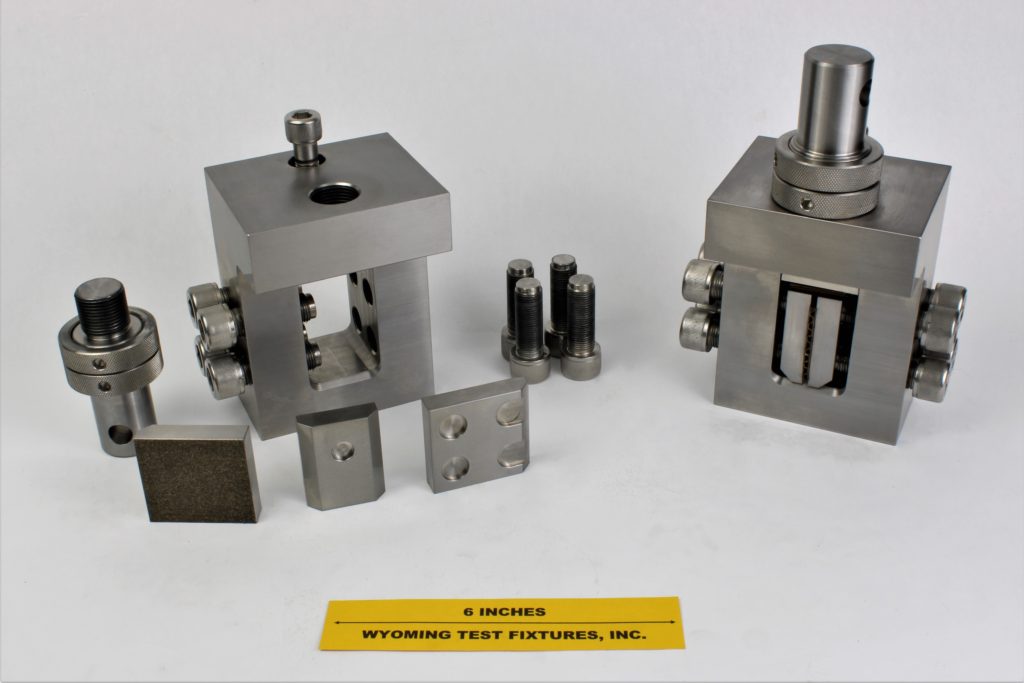
Fig.8: Adjustable Combined Loading Shear (CLS)Test Fixtures with one half shown disassembled at the left.
Sources of Additional Information:
1) ASTM Standard D7078-05 (2005), "Standard Test Method for Shear Properties of Composite Materials by the V-Notched Rail Shear Method," American Society for Testing and Materials, West Conshohocken, Pennsylvania (first published in April 2005).
2) Adams, D. O., Moriarty, J. M., Gallegos, A. M., and Adams, D. F., “Development and Evaluation of the V-Notched Rail Shear Test for Composite Laminates,” Federal Aviation Administration Report DOT/FAA/AR-03/63, FAA Office of Aviation Research, Washington, D.C., September, 2003.
3) Hussain, A. K. and Adams, D. F., “An Analytical and Experimental Evaluation of the Two-Rail Shear Test for Composite Materials,” University of Wyoming Composite Materials Research Group Report UW-CMRG-R-98-105, February 1998.
4) Adams, D. O., Moriarty, J. M., Gallegos, A. M., and Adams, D. F., “The V-Notched Rail Shear Test,” Journal of Composite Materials, Vol. 41, No. 3, February 2007, pp. 281-297.
5) Adams, D.O., Gallegos, A.M, Moriarty, J.M., and Adams, D.F., “A V-Notched Rail Shear Test for Composite Laminates,” Proceedings of the 2002 SEM Annual Conference, Milwaukee, WI, June 2002.
6) Adams, D.O., Moriarty, J.M., Gallegos, A.M., and Adams, D.F., “Development and Evaluation of a V-Notched “Rail Shear Test,” Proceedings of the 2002 SAMPE Technical Conference, Baltimore, MD, November 2002.
7) Hussain, A.K., and Adams, D.F., “The Wyoming-Modified Two-Rail Shear Test Fixture for Composite Materials,” Journal of Composites Technology and Research, Vol. 21, No. 4, October 1999, pp. 215-223.
8) Hussain, A.K., and Adams, D.F., “Experimental Evaluation of the Wyoming-Modified Two-Rail Shear Test Method for Composite Materials,” Experimental Mechanics, Vol. 44, No. 4, August 2004, pp. 354-364.
9) Hussain, A.K., and Adams, D.F., “Analytical Evaluation of the Two-Rail Shear Test Method for Composite Materials,” Composites Science and Technology, Vol. 64, 2004, pp. 221-238.

